www.LaserFX.com Home Page - CLICK HERE

  Home Page >> How Laser Shows Work > Laser Projector

Search LaserFX.com - CLICK HERE Site Map - CLICK HERE
LaserFX.com Home Page - CLICK HERE
Tech Talk Section - CLICK HERE
Laser Safety - CLICK HERE
Laser Show FAQ - CLICK HERE
How Laser Shows Work - CLICK HERE

Introduction

How Lasers Work

Laser Projector

Scanners

Control console

Graphics system

Outboard Equipment

Glossary

 
Laser Science Projects - CLICK HERE
Laser Images Gallery - CLICK HERE
Laser Show Calendar - CLICK HERE
Where To Hire a Laser Show - CLICK HERE
Information & Education - CLICK HERE
Updates Page - CLICK HERE
Member Services - CLICK HERE
LaserFX.com Banner Ads - CLICK HERE
About Laser F/X - CLICK HERE
Contact Us - CLICK HERE


How Laser Shows Work - Laser Projector

    The laser projector is where the laser beam is controlled and scanned to produce the effects you see in the show.

   Laser Projector block diagram


In the block diagram above, the laser beam first encounters the shutter (marked S on the diagram).   This is typically an actuator or solenoid designed to turn the beam on or off (at slow speeds).  In most modern laser projection systems the shutter is gravity or spring- loaded as a safety feature.  In the event of a power failure to the laser projector, the beam is blocked by the gravity or spring-loaded shutter so that no projection can take place.

Actuators
   
One of the most common devices in laser projection equipment is the actuator - used for shutters, colour boxes and in beam tables.  An actuator can be thought of as a limited rotation electrical motor that only moves a few degrees when power is applied.  In a beam table, the shaft of the actuator is fitted with a lightweight arm that has a mirror glued to the end of it.   It is mounted below a laser beam at a 45 degree angle to the beam, such that the mirror is close to, but not touching, the laser beam.  Sending an electrical signal to the actuator pulls the arm (and mirror) into the beam so that the laser is deflected at 90 degrees to it's original line of travel and into other optical components.
Actuator animation


Colour Control

    The laser beam next encounters the colour control area. Laser shows either use a tandem laser pair (an Argon laser for the blue and green and a Krypton laser for the red) where the beams from the two lasers are combined to form a "white" beam; or a white light laser which produces red, green and blue from one laser.  Colour control can be either subtractive - where unwanted colours are subtracted from the beam; or additive where colours are added to make the desired colour.

Laser Lines

    Laserists (and scientists) speak of "lines" (measured in nanometers - nm for short) rather than colours, as the colour of the beam perceived by the eye is a function of the frequency of the photon oscillations.  A HeNe laser typically produces a very pure red colour at 632.5 nm.  Below is a chart showing some of the most common lines produced by lasers used in light shows.


Simplified laser line (colour) chart

    A large and very detailed chart (in .tif format) showing all of the lines emitted by various types of lasers (contributed by one of our members, Brian) is available for download. SpectrumchartV10.zip (246 KB)

     The most typical forms forms of colour control used in laser shows (when you have a 'white' beam) are a colour box and a PCAOM (PolyChromatic Acousto Optic Modulator).

Colour Box

    The colour box is a subtractive device that uses three actuators with dichroic filters mounted on the ends of the arms (one cyan, one magenta and one yellow dichro) to select one of seven colours that will be displayed.  It has a relatively slow response time as it is a mechanical device thus it can only produce a limited number of colour changes in each frame.  It has the advantage of low cost and simple implementation.
    Depending on which colour is desired in the output, one or more of the dichroic filter is inserted into the beam to subtract (block) the unwanted colour(s).  The colour box can output white, red, green. blue, cyan, magenta and yellow colours.

An animation of a Colour Box showing how different combinations of Dichros produce the colours


PCAOM

    At the other end of the scale is the Poly Chromatic Acousto Optic Modulator (PCAOM), a solid state, in-line device that allows for continuous brightness control of multiple laser lines to generate 16.7 million or more colours at MHz speeds.  The PCAOM acts as a bulk diffraction grating which gives brightness control over the individual laser lines.  Just as a TV set combines variable brightness of Red, Green and Blue to make the different colours you see on the screen, the PCAOM allows for variable brightness control of a number of laser lines (colours) that are added to create the desired output colours for projection.  For example, one can combine 100% of the red line(s) with 50% of the green line(s) to produce an orange beam.  
    A PCAOM consists of a driver card or electronics package that takes the colour control signals and converts then to an RF signal that is fed to the cell.  The cell is a crystal with a transducer bonded to it, that is inserted at the correct angle into the laser beam.  The PCAOM has the advantages that it can produce 16.7 million (or more) colours, has very high response speed as it is a solid state device thus allowing for multiple colours and blanking within a single frame.

PCAOM driver and cells photo
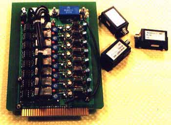
Eight line PCAOM driver card with 3 PCAOM cells to it's right - Photo courtesy of MVM


Beam Table

STP8 actuator photo
STP8 Actuator - Photo courtesy of MediaLas

    Beam effects, especially those that are to be directed at bounce mirrors, are usually generated by a beam table. The beam table acts as a digital beam switching device since the actuators (see photo on left and animation above) can only be in or out of the beam.
    The beam table system uses the mechanical movement of the actuator (with it's arm and mirror) to the same position each time, to deflect the beam to optics on kinematic (X-Y adjustable) mounts.  These beams are very stable and accurate as they can only be on or off due to the switching nature of the actuator. The kinematic mounts allow the beam to be precisely positioned so as to target remote bounce mirrors or other outboard effects.  The beam table area can also contain other optical effects such as lumia wheels and diffraction gratings.

    In the Projector Block Diagram above, a four position beam table consisting of actuators A1 to A4 is shown as an example - large professional projectors may have up to 16 beam table positions.  When one of the actuators is energized, the mirror on the end of the arm deflects the beam towards the two kinematic mounts positioned behind it.  If the first mount is equipped with a 50/50 beamspliter, and the second mount is equipped with a mirror, the beam table position outputs two beams (each half as bright as the input beam).  Beam tables used with higher power lasers can have a combination of beam splitters and mirrors to output 4 (quad position) or more beams from each beam table position.
    The output beams can be precisely positioned with adjustment screws on the the back of the kinematic mounts, so as to target remote mirrors that can then deflect the beam in a different direction.  Using a four position beam table equipped with 50/50 splitters and mirrors, one can generate 8 beams out.  By deflecting each of these beams from a remote bounce mirror, it gives the impression that there are many more beams in the venue (16 beams if each beam is bounced once from a remote mirror).
    The beam table actuators can also be sequenced to "chase" the beams around the venue.  With a high speed sequence (where each actuator is engaged 15-20 times a second), the illusion that the beam table is projecting 8 beams at the same time is created.  The beams are being switched on and off too fast for the eye to see thus it appears that all the beams are on at the same time.

Beam Table Colour

    Some beam tables use "fixed colour" where the 50/50 beamspliter is replaced by a dichroic filter.  When the actuator energizes, the dichroic deflects a beam of a fixed colour while the mirror behind it deflects the remaining colours passed by the dichroic filter.  Whenever a particular beam table position is activated, it always outputs the same colours.
In a beam table equipped with 50/50 (or other combinations of) beamspliters, each position can output any colour - all beams from that position will be the same colour).  By synchronizing colour changes in the colour control system with the movement of the beam table actuators, each position can display any desired colour that the system can generate.


Scanning System

    The most important part of laser projection system are the galvos, more commonly called scanners. Graphics, animations, abstracts and dynamic beam effects are generated by X-Y scanning of the laser beam.  The scanning system is covered in more detail on the Scanning Systems page.


Support Electronics

   The projector cabinet (or a separate electronics rack) usually includes all of the power supplies, cooling fans and driver cards used to make the projection system work. Support electronics may also include safety features such as power-off interlocks and scan fail detectors.

[ Laser and exciter | Projector | Scanners | Control console | Graphics system | Outboard Equipment ]


© 1996-2008 Laser F/X International and LaserFX.com - All rights reserved.
Logos and trademarks are the property of their respective owners - used by permission.