|
Very Basic
Laser Show
The most basic. low cost laser show you
can build is based on 'spyrograph' patterns generated by rotating mirrors
mounted on DC motors. The information is provided here for fun and
experimentation as this effect is rarely used in professional laser shows.
PARTS:
A HeNe or diode laser (you can use a laser
pointer)
Two small DC motors and hardware to mount them
Two variable voltage DC power supplies for the motors (model train power
supplies work well)
Two small lightweight front surface mirrors
(preferably circular)
Some 5 minute epoxy glue
You will need at least two DC motors that
can rotate at speeds between 300 and 3,000 RPM and two independent DC power
supplies. Model train transformers work well for this application as the
more modern ones use pulse width modulation to control the speed of the
trains. Switches that allows the motors to go in forward or reverse also add
to be effects generated.
Obtain two thin, round Front surface mirrors at least
25mm [1"] in diameter. Mount these on the ends of the motor shafts
[epoxy works well]. When you mount then. you don't want then exactly square
and true to the shafts, you want then slightly tilted so that a laser
reflected from the spinning mirror will draw a small circle. If you have
access to a lathe, you can fashion a mount that allows you to adjust the
'tilt' of the mirror and the size of the circle that it will draw.
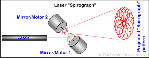
Once the mirrors are mounted and the glue has dried,
place the motors on brackets so that the mirrors face each other with a
short distance [25mm - 1" or less] between them. The motor/mirror
assemblies should also be set up in such a way that the angle between them
can be adjusted. Send the laser beam into the first mirror and start it
rotating. Now adjust the angle of the first motor/mirror assembly so that
the circle it is projecting falls onto the mirror of the second assembly.
When this step is complete, start the second mirror spinning and adjust the
angle of the second assembly so that the pattern is projected without
hitting any part of the first mirror/motor assembly [see diagram].

By varying
the speed of the mirror, you are controlling the frequency of the circle
that it draws; by changing the direction you get added effects. The effect
on your wall or screen is produced by spinning a circle in a circle. The
'beats' between the frequencies of the two circles control the complexity of
the patterns produced.
You can increase the complexity and range of the effects by
adding a third and even a forth motor/mirror assemble with variable DC power
supply. If you do add an additional assembly, you have to be sure that it
deflects the bean into a very small circle so that you do not 'overfill' the
last mirror in the array.
To add yet another simple variation to your
basic laser show, you can add chopping. Make a small disk that has slots or
teeth around the perimeter [a miniature circular saw blade works]; you can
also use a miniature DC fan. Mount this securely on a separate motor with a
separate variable DC supply. You might want to choose a motor that can go
quite fast for this application. If you place this in the beam before it
hits the first spinning mirror, the spinning slotted or toothed disk will
cause the laser to 'pulse' on and off. This causes the spyrograph to appear
as a series of dashed lines. With the right combination of speeds, traveling
black segments will move through the spyrograph patterns adding to the
effects.
The number of slots or teeth around the
perimeter of the disk will determine how many times per revolution the laser
is 'pulsed' - more teeth/slots gives more pulses. If you use a disk with
triangular teeth like a circular saw, putting just the tips of the teeth
into the beam will produce very short off pulses. Moving the disk so that
the laser is closer to the bottoms of the teeth will produce longer off
pulses adding to the effects you can produce.
Most
of the information and ideas in the Hobby Archives have been contributed
by hobbyists and experimenters. If you have any comments or ideas to
share, please contact us by E-mail.
DISCLAIMER:
Some of the information in the Backstage area is provided by the persons or
companies named on the relevant page(s). Laser F/X does NOT endorse or
recommend any products/services and is NOT responsible for the technical
accuracy of the information provided. We provide this information as a
service to laserists using the Backstage area.
[ Introduction
| Hobby
Archives | Hobby
FAQ | Laser
Construction ]
|