|
Laser
Science Projects
Basic Laser Science Projects
The Laser
science projects on this page are at the basic level and require a
minimum of equipment and parts to construct.
Measurement
of small angles using a laser as an optical lever
In this set-up
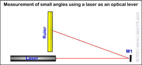
the laser beam is sent from the laser to a mirror about 1 meter away
from the laser then reflected back to a ruler located next to the laser
[see diagram]. When a laser is reflected by a mirror placed in its beam
at a forty five degree angle, the beam is deflected 90 degrees as the
angle of reflection is two times the angle of incidence. If the mirror
[M1 in the diagram] is rotated one degree the beam will be deflected two
degrees causing the spot to move on the ruler.
PARTS
A HeNe or diode laser [you can use a laser pointer]
A ruler calibrated in mm
A mirror [preferably front surface]

- If you measure the distance the spot moved on the
ruler can you derive a formula that will tell you how much the
mirror has moved in degrees?
- What would be the maximum resolution [accuracy] of
this system and what are the limiting factors on resolution?
- Can you list some applications for an optical lever
device that can measure angular displacement with great accuracy?
Laser
range finder
A range finder is a device
that allows you to find the distance from your position to an object
without using a measuring tape.
PARTS
A HeNe or diode laser [you can use a laser pointer]
A 50/50 beam splitter [you can substitute a microscope slide but it
will not work as well as a beamsplitter]
A protractor and a short rod or piece of metal to make an indicator
A mirror [preferably front surface]
A board a little longer than 1 meter to mount the laser and optics
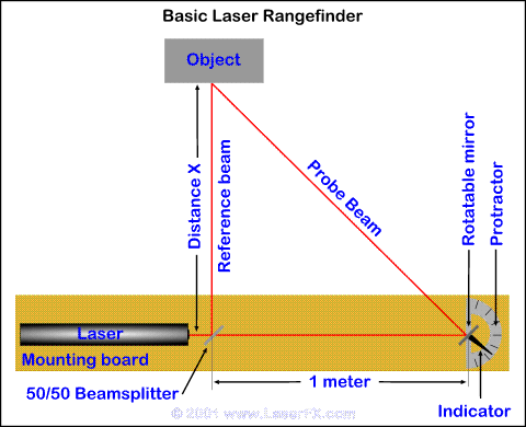
For this set-up (see
diagram) you should mount the laser on a piece of board or plywood a little longer
than one meter. Mount a 50/50 beam splitter in front of the laser to
split the beam into two beams. You can use a microscope slide but it
will not split the beam brightness exactly in half, the transmitted beam will be
brighter than the reflected beam. The beam from the beamsplitter must be
deflected at exactly 90 degrees from the incoming laser beam - this is
the reference beam.
Now mount the mirror one meter away from the beamsplitter
on a post that allows it to rotate - this is the probe beam .
You should attach an indicating arm to the post and mount a protractor
or degree scale so you can measure how many degrees the mirror has been
rotated. Adjust the scale so that it reads zero when the two beam are
parallel. This is easiest to do if you point the range finder at a wall
three to four meters away and measure that the spots from the two beams
are one meter apart. You can then adjust the indicating arm on the
protractor to read zero degrees.
Place an object at an unknown distance (X) from the
range finder and adjust the object so that the laser spot from the
reference beam is clearly
visible on the object. Now adjust the movable mirror so that the probe beam is exactly overlaid on the reference beam (the two spots are on top
of each other). You can now read off the displacement of the mirror in
degrees from the protractor.

- What type of triangle do the beams of the range
finder form?
- Given the reading in degrees, how would you derive
a formula that would allow you to measure the distance to the
object?
- What would be the maximum and minimum distances
that the range finder would be accurate?
- What modifications would you make if you wanted to
measure shorter distances? Longer distances?
- What applications would a device like this have?
- What is the theoretical accuracy of this range
finder and what are the factors that limit it's resolution?
Parts Sources
The most important part you
will need is a laser. Most High School science departments will have a
HeNe laser and you may be able to use it - ask your teacher. You can
also obtain HeNe lasers from a number of on-line sources, from surplus
houses, and from ads in electronics magazines.
You can use a 'laser pointer' for these projects - small
pen shaped devices with a laser diode mounted in one end. These
are available from many sources such as AV companies and stores like Office Depot, Office Max, Radio Shack and Staples.
Optics parts such as front surface mirrors and
beamsplitters can be obtained from optics vendor, as well as from
some electronics surplus houses.
[ Introduction
| Bibliography | Glossary of
Terminology | Laser
safety overview | Other
applications of lasers | Selected
laser
related web sites | Basic laser
science projects | Intermediate
laser science projects | Advanced
laser science projects | Illustrations
for laser science projects ]
|