|
Laser
Science Projects
Advanced
Laser Science Projects
The Laser
science projects on this page are at the advanced level and require more
equipment and parts as well as some knowledge of electronics to
construct. They are more complex than the than the basic and
intermediate projects.
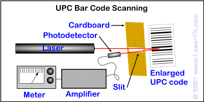
Demonstration
of the principals of bar code scanning
The UPC (Universal Product Code) code is a series
of bars or lines that are printed onto many products and identify the
product with a unique serial number. This is a more advanced
project as it requires some knowledge of, and skill with, electronics.
PARTS
A HeNe or diode laser (you can use a laser pointer)
A photocell or phototransistor
A circuit to detect and amplify the output of the detector/transistor
A way to display the output of the circuit such as a LED or a meter
First mount the phototransistor into a short length (2 to 3
cm) of black plastic tube to form a light shield. Now place the
laser at a slight angle to a slit in a piece of cardboard or opaque plastic so that you can drag a UPC code past
the slit. Place a
piece of white paper over the slit and point the laser at the paper;
then point the phototransistor at the laser spot, adjusting the angle of
the phototransistor (and the sensitivity of the amplifier circuit) until you get
the maximum signal.
Make a test UPC symbol by Xeroxing one from a product with
an enlarging copier so it is 4 or 5 times larger than the original -
this will simplify your experiment.
- If you drag the test UPC code past the slit, what do you
see on the meter or LED?
- What is the optical principal at work here?
- How can you adjust the circuit or modify it to improve the output?
- What improvements can you make to the basic design to increase the
light gathering of the phototransistor?
- What improvements can you make to this project to reduce
interference from room light?
- How can you modify the output from the phototransistor and
detector circuit to provide more useful information from the UPC
code?
- What other applications can you think of for this type of
technology?
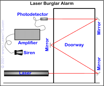
Laser
"burglar alarm"
A laser beam can be used a a "burglar
alarm" to detect unauthorized access. This is a more advanced
project as it requires some knowledge of, and skill with, electronics.
PARTS
A HeNe or diode laser (you can use a laser pointer)
Three (or more) small mirrors on mounting brackets
A photocell or phototransistor
A circuit to detect and amplify the output of the detector/transistor
A device such as a bell or siren to provide the alarm signal
First mount the phototransistor into
a short length (2 to 3 cm) of black plastic tube to form a light
shield. Now mount the small mirrors around the doorway or other
opening to be protected as shown in the diagram (only 3 mirrors are
shown, you can use more). Mount the laser so that the beam is
deflected back and forth across the opening by the mirrors and into the photo detector.
You will need to create an electronic circuit that will
amplify the output of the photocell or photo transistor. The
output needs to be set up in such a way that it is on when the beam is
off (and vice versa). The output needs to be sufficient so that it
can drive the bell, buzzer or siren you are using to give the
alarm. When the beam is broken, the alarm should sound.
- What is the optical principal at work here?
- What improvements can you make to the basic design to increase the
light gathering of the phototransistor?
- How can you adjust the circuit or modify it to improve the output?
- What improvements can you make to this project to reduce
interference from room light or sunlight?
- What methods can you devise to defeat this kind of device?
- What methods can you devise to improve the performance of this
kind of device or make it more difficult to defeat?
- What other applications can you think of for this type of
technology?
Parts Sources
The most important part you
will need is a laser. Most High School science departments will have a
HeNe laser and you may be able to use it - ask your teacher. You can
also obtain HeNe lasers from on-line vendors, from surplus
houses, and from ads in electronics magazines.
You can use a 'laser pointer' for these projects - small
pen shaped devices with a laser diode mounted in one end. These
are available from on-line vendors, AV companies and
even stores like Office Depot, Office Max, Radio Shack and Staples.
Optics parts such as front surface mirrors and
beamsplitters can be obtained from on-line vendors as well as from
some electronics surplus houses.
Electronics parts can be obtained from suppliers such
as Radio Shack or a local electronics vendor.
Simple mounts for the parts or mirrors can be fabricated
from wood or angle brackets obtainable form hardware vendors such as
Home Depot or Builders Square.
[ Introduction
| Bibliography | Glossary of
Terminology | Laser
safety overview | Other
applications of lasers | Selected
laser
related web sites | Basic laser
science projects | Intermediate
laser science projects | Advanced
laser science projects | Illustrations
for laser science projects ]
|
