www.LaserFX.com Home Page - CLICK HERE

 Home Page >> Detailed Laser Safety > Safety Archives

Search LaserFX.com - CLICK HERE Site Map - CLICK HERE
LaserFX.com Home Page - CLICK HERE
Tech Talk Section - CLICK HERE
Basic Laser Safety - CLICK HERE

Introduction

Eye and Skin Hazards

Electrical Fire and Flood hazards

Basic Safety Precautions

Laser Pointer Safety

Laserist Introduction

Laser Safety Archives

Laser Safety Regulations

Laser Safety Links

 
Laser Show FAQ - CLICK HERE
How Laser Shows Work - CLICK HERE
Laser Science Projects - CLICK HERE
Laser Images Gallery - CLICK HERE
Laser Show Calendar - CLICK HERE
Where To Hire a Laser Show - CLICK HERE
Information & Education - CLICK HERE
Updates Page - CLICK HERE
Member Services - CLICK HERE
LaserFX.com Banner Ads - CLICK HERE
About Laser F/X - CLICK HERE
Contact Us - CLICK HERE


Detailed Laser Safety - Safety Archives


An Electronic Approach to Safer Scanning
By L. Michael Roberts

Abstract

To improve the safety of laser shows, especially in jurisdictions where audience scanning is permitted, it is desirable to monitor the behavior of the scanners electronically.  If a malfunction is detected, then the system can be shut down.  This paper covers the theoretical considerations of such systems.


Introduction

Laserists depend on their scanners to create graphics, animations and scanned beam effects.  If the scanning system were to malfunction or fail, a high power beam could potentially be projected into an unsafe area and possibly injure spectators.  The scanners are electronic devices and are thus amenable to hardware monitoring circuitry that can take action to shut down emissions far faster than the human operator.  Such electronic safety systems are very useful even in situations where no audience scanning will take place.


Basic Systems

Professional scanners are equipped with position detectors as these are necessary for the precise operation required to produce images.  The position of the scanner is detected and compared to the input signal.  An error is then generated and this is used to correct the position of the scanners.
The first step is to isolate the position detection system and determine the voltage and current parameters of this signal.  Many scan amps provide a test point or an output where this signal can be accessed.  Care must be taken not to load or distort this signal in any way as that will effect the proper operation of the scanners.
Once this signal has been accessed, we must do some simple signal processing to make it useful. This might include amplifying or attenuating the signal or converting it to a more useful voltage. It would be desirable to add optoisolation to the input to prevent our hardware from interfering with the correct operation of the scanners.

Diagram 1

Diagram 1 shows a block diagram of how such hardware might work.  The output of the detector is used to control a small relay that is the last item in line before the shutter.  When the detector senses that the scanner has failed, the relay opens and the spring or gravity loaded shutter closes preventing projection of the beam.  The output of the detector should be high when the scanner is functioning correctly so that it holds the relay in.  In the event of a power or other failure, the relay will open closing the shutter to provide an additional measure of safety.  
While this device would be helpful in improving scanner safety, it is not particularly useful as it can only monitor one scanner.

Diagram 2

Diagram 2 shows and enhanced system that can monitor both the X and Y scanners.  This is accomplished by adding a second set of signal conditioning and detection circuitry along with simple logic.  Given that the output of the detectors are high when the scanners are functioning, the logic uses a simple IF X=1 AND Y=1 THEN Output=1 rule to keep the relay pulled in.  If either scanner fails, the relay opens and the shutter closes.
This very simple system does not address one critical factor.  It is possible for the scanners to stop moving and for the resulting beam to still be quite safe.  An example of this is a scanned beam sequence effect where the beam may dwell for a short period of time in one position, 1/20 to 1/10 of a second, before stepping to the next position in the sequence.
Disregarding the speed at which the shutter moves for the moment, the electronics would almost instantaneously detect a lack of scanner movement and attempt to shutter the beam. This could lead to a condition where the beam sequences only shows the laser movement between positions and not the beam positions themselves.

Diagram 3

Diagram 3 shows how this problem might be addressed.  By adding a small delay to the relay control signal, effects where the scanners stop moving, but yet where the projected effect is still safe, can be accounted for.  The delay circuit might be something very simple such as a capacitor or something more complex where more accurate control of the delay timing is possible.  The time constant of the delay would have to be selected such that safe effects could still be projected, but scanner failures would be detected and the shutter closed.


Professional Systems

The systems described above are limited in their application due to a number of factors.  They do not take into account the length of time it takes for the shutter to close.  This could vary greatly from system to system due to the type and speed of the device, and the height above the beam.  Even in the best case where an actuator driven shutter is positioned just above the beam, the delay between scanner failure and the extinction of the laser output could be 1/10 of a second or possibly more.  In an audience scanned effect from a medium power laser where the scanner fails while the beam is in the audience zone, this could be enough time to cause vision damage.
The basic systems described above do not take into account cases where a beam can be stopped for a long period of time and still remain perfectly safe.  An example of this would be using scanners to target bounce mirrors that are located three or more meters above the audience, or when targeting an outboard effects such as a grating effect where the deflected beam from the grating is in a safe area..  A professional system would have to take these factors into account.
Despite these limitations, such basic systems remain useful in the absence of a professional scan failure detection system as they would react more quickly than a human could - even if that reaction times is unsatisfactory for complete safety.  This is important since laserists are not always able to watch the beam output due to the requirement to adjust computers and controllers and other performance distractions.
A professional system must be capable of extinguishing the beam within the time frame necessary before vision damage can occur and must take into account effects where the scanners are paused or stopped and yet the scanned output is still safe.  This is where the PCAOM comes to our rescue.  The PCAOM is a very high speed device capable of extinguishing the beam in milliseconds if there is an unsafe scanner condition.
It is beyond the scope of this article to discuss in detail how such a scan failure system might be constructed.  It would require the same signal condition and detection as outlined above but in addition, would have to incorporate microprocessor logic to determine if the scanners are operating safely and if not, turn off the colour control signals to the PCAOM to blank the beam.


CatSafePro Scan Fail Detector

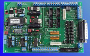
One such device on the market is the CatSafe and CatSafePro from MediaLas in Germany.  These systems incorporate microprocessor controlled logic to detect scanner failure.  In addition, the CatSafe systems offer a adjustable Safe Area Window (SAW).  This allows the user to set areas in which the scanners can remain motionless for targeting bounce mirrors or outboard effects, without causing the PCAOM to blank the beam.
The basic CatSafe is a small circuit board that requires a bit of work to integrate into the system but provides a professional level of scanner failure protection.  The CatSafePro is a larger board that incorporates the same circuitry and scanner failure detection, but is simpler to integrate into a projector as it has ILDA standard input and connectors for the most popular scanners and PCAOM.


Summary

To improve the safety of laser shows, especially in jurisdictions where audience scanning is permitted, the behavior of the scanners should be monitored electronically.  The monitoring circuit would extinguish the laser beam if the scanners fail.  Basic systems which detect scanner failure and close the shutter are useful in adding an extra measure of safety to the show but may not react fast enough to prevent vision damage.  Professional systems use sophisticated microprocessor control of the PCAOM and take into account conditions where the scanners have stopped moving and yet the effect is still safe.
As laserists, we must all be concerned with show safety and some form of scanner failure detection should be incorporated into the laser projection system.


[ Introduction | Eye and Skin Hazards | Electrical fire and flood hazardsBasic safety precautions | Laser Pointer Safety ]
[ Laserist Introduction | Laser Safety Archives | Laser Safety Regulations | Laser Safety Links ]


© 1996-2008 Laser F/X International and LaserFX.com - All rights reserved.
Logos and trademarks are the property of their respective owners - used by permission.