www.LaserFX.com Home Page - CLICK HERE

  Home Page >> How Laser Shows Work > Scanners

Search LaserFX.com - CLICK HERE Site Map - CLICK HERE
LaserFX.com Home Page - CLICK HERE
Tech Talk Section - CLICK HERE
Laser Safety - CLICK HERE
Laser Show FAQ - CLICK HERE
How Laser Shows Work - CLICK HERE

Introduction

How Lasers Work

Laser Projector

Scanners

Control console

Graphics system

Outboard Equipment

Glossary

 
Laser Science Projects - CLICK HERE
Laser Images Gallery - CLICK HERE
Laser Show Calendar - CLICK HERE
Where To Hire a Laser Show - CLICK HERE
Information & Education - CLICK HERE
Updates Page - CLICK HERE
Member Services - CLICK HERE
LaserFX.com Banner Ads - CLICK HERE
About Laser F/X - CLICK HERE
Contact Us - CLICK HERE


How Laser Shows Work - Scanning System

    The most important part of laser projection system are the galvos, more commonly called scanners. Graphics, animations, abstracts and dynamic beam effects are generated by X-Y scanning of the laser beam using galvanometer scanners. 

High speed galvanometers photo
High speed galvanometers with various mirror sizes
 Photo courtesy of Cambridge Technology Inc.

    The galvanometer (often abbreviated to galvo) is a current-sensitive device that operates in a similar manner to an analogue meter. In an analogue meter, a small coil of wire is wound around a lightweight aluminium bobbin that is suspended in the gap of a permanent magnetic field by means of pivots and bearings. The coil has a thin needle attached which extends over an indicating face which is is the part of the analogue meter which you see.
    When electrical energy is applied to the coil, it develops a magnetic field that will act against the field in the gap causing the coil to move the indicating needle proportionally to the current applied. Some meters are designed to be at rest at one end of the scale (such as analogue VU meters), while others are at rest in the centre of the scale (an analogue FM tuning indicator for example).
    The first type of meter is a unipolar device as it reacts only to an increase in the current applied; while the second type of meter is a bipolar device as it reacts not only to the current applied, but also the polarity of the current. When the signal is negative, the indicating needle moves in one direction away from its central position: when the signal is positive, it moves in the opposite direction away from its central position.
    Unfortunately meter movements are too small, to slow, and to delicate to allow us to attach a mirror and control laser beam deflection. We must use a more rugged type of device, a scanning type galvanometer. 
Galvos can be thought of as very high speed, current sensitive, limited rotation electrical motors.  The amount of rotation (within the rotational limits of the galvo) is determined by the amount of current applied; with the direction of the limited rotation controlled by the polarity of the current applied.  Galvos (scanners) are a current-sensitive bipolar device that are at rest in the centre of their limited rotation.

Usage Note: The words galvo or galvanometer refers to the basic galvanometer itself, without an attached mirror.  Scanner refers to a galvanometer that has a mirror attached to it such that it can deflect a laser beam by applying appropriate control signals.

    The type of galvos used in laser scanning systems typically use a moving magnet or soft iron rotor.  Since the shaft has to reciprocate (move back and forth) many thousands of times per second, it would be very difficult to build a rugged device that used a moving coil due to the flexing of the wires that would be needed to supply the current to the coil.  Laser scanners are build "inside out" from the typical meter movement described above; the coils are wound on the outside pole pieces (armature), and a magnetic or soft iron rotor, mounted in small precision bearings and suspended in the gaps of the pole pieces, moves the shaft with the mirror.  The shaft has a spring or torsion bar to return the rotor to the central at-rest position when no current is applied.

Cross section of a galvo/scanner diagram
Cross section of a typical galvo

The two permanent magnets crate a strong flux in the gaps of the central pole pieces of the armature.  The rotor moves - moving the shaft with attached mirror - in response to variations in this magnetic flux caused by current applied to the drive coils.

Types of scanners

    There are two major types of scanners used in laser light shows - open loop and closed loop.  A scanner is open loop if no position detection device is used, and closed loop if a position detection device is used.

Open loop

   Open loop scanners are typically built as shown in the diagram above.  The rotor has a shaft running through it with top and bottom bearings.  The shaft protrudes outside the housing of the scanner so that a mirror can be attached to the shaft.

Open loop scanner diagram
Open loop scanner block diagram


When a current is applied to the drive coils, the shaft moves in the direction determined by the polarity of the signal, and in an amount proportional to the current applied (within the limitations of it's travel).  The movement is relatively predictable but there is no way to know exactly where the shaft with the attached mirror is.  Open loop scanners are thus useful as actuators and for beam steering or simple scanning applications, but lack the precision needed for accurate applications such as laser graphics.

Closed Loop

   The closed loop scanner adds an additional element.  The shaft is fitted with a position detector that can determine where the scanner is within it's range of motion.  In modern high-speed scanners, the position detector uses an optical system with a vane that occludes the light from an LED falling onto a photo sensor.  As the shaft moves through it's range of motion, more or less light falls on the photo sensor generating a signal that is proportional to the position of the shaft and it's attached mirror.


Closed loop scanner block diagram

   In the diagram above, the LED is shown in green and the photo detector in light blue with an occluding vane attached to the shaft between then.  The closed loop scanner amplifier is also more complex than the typical open loop scanner amp.
    The input signal is sent to the scanner drive stage circuit after passing through the input conditioning circuit.  The position of the shaft (and it's attached mirror) is derived from the photo detector in the position detection circuit, which sends that signal to a position correction circuit.  The position correction circuit compares the actual position of the mirror, with the position the mirror should be in according to the signal from the input conditioning circuit.  It then generate an error correction signal and sends that to the scanner drive stage where it is combined with the input signal.  The drive stage provides the current to the coils in the scanner to move the mirror.
    The position of the mirror is thus compared in real time with the input signal and corrected for any inaccuracy.  This allows the very precise and accurate control of the mirror that is necessary for projecting laser graphics.  Naturally, since this is a mechanical system, there are limits to how fast the mirror can be moved. 


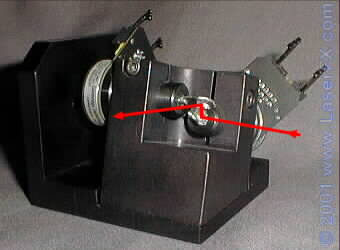
Scan Head

    So far, we have covered only one axis of scanning - one scanner can only take a laser beam and deflect it in a single plane drawing a line.  In order to create images, we need to control the position of the laser beam, both horizontally (X axis) and vertically (Y axis).  Laser projectors use a pair of scanners mounted orthogonally (at right angles to one another) to control X and Y axis deflection.

Cambridge Technology CT6800 scanners in an orthogonal mount

Photo of the Cambridge Technology CT6800 scanners in an orthogonal mount which is attached to a heatsink.  A line has been drawn in to show the path the laser beam takes through the X-Y scanners.

  The laser beam first encounters the X (horizontal) scanner.  This deflects the beam at right angles to it's line of travel and upwards onto the Y mirror.  If the X scanner were fed a sine wave, the movement of the mirror would draw a line on the Y (vertical) mirror placed above the X mirror.  The Y mirror takes the line drawn by the X mirror and moves it vertically.  If the Y scanner were fed with the same sine wave as the X scanner, the projected image would be a line at a 45 degree angle.  If the two sine waves were out of phase, a circle would be drawn.
  Using an X-Y scanning system fed from analogue oscillator circuits, the position of the beam can be controlled so as to allow for the projection of complex abstracts.  By digitizing and storing images in a computer, complex graphics and animations can be projected - see the Graphics Systems page.


Blanking

    In addition to the scanners, a separate device is used for blanking -- rapid on/off control of the laser beam. In an un-blanked system, all letters in a word (or all parts of an image) drawn by the laser are joined together like cursive script. In a blanked system, the letters are individual (not connected) like printing. In actual fact the letters are still joined by a line however the laser is turned off as it jumps between segments by the blanking device so that the join line is not visible.

Un-blanked and blanked text

The word "laser": without blanking at the top - note the join lines between and within the letters.  The bottom image is blanked to eliminate the join lines.

    The most common form of blanking for many years, was to send the beam through a third scanner which deflected it to a pair of small mirrors set at right angles to one another (a corner reflector).  The corner reflector sent the beam back to the scanner and from there it was deflected into the X-Y scan pair.  This arrangement formed an optical switch as any movement of the scanner caused misalignment of the beam through the corner reflector, turning the beam off.  This method is still used in some high power laser projectors as there is a limitation to the amount of power a PCAOM cell can handle, and the corner reflector blanking system has little optical loss.
    Most newer laser projectors, especially full colour systems, use the PCAOM for blanking as well as colour control.  Since the PCAOM can control the brightness of all the laser lines at MHz speeds, it is trivial for it to extinguish the beam for the short periods of time required to blank unwanted sections of the image.

More technical information about scanners can be found on the Scanning Systems page in the Laser Show Systems section Backstage.


[ Laser and exciter | Projector | Scanners | Control console | Graphics system | Outboard Equipment ]


© 1996-2008 Laser F/X International and LaserFX.com - All rights reserved.
Logos and trademarks are the property of their respective owners - used by permission.