|
|
|
|
|
Home Page >>> Backstage Area >> Laser Hobbyists > Hobby Archives - 60X Fan Mount |
|
60X Fan Mount
This page was contributed by Mark Schweter schweter@mail.bright.net
Introduction This project was the result of a need for a "quick-fix" fan interface for my new 60X head. Previous experimentation by Steven Roberts, and myself, had resulted in mounts with a less than "professional" appearance. The design considerations were: A clean finished appearance, L.Michael Robert's information on fan selection and Karl Rothweiler's report of an "official" fan riser he had seen.
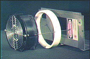
Parts & Fabrication |
| Fan | Model No. | AC volts | Watts/Amps | Rotron Part No. | Newark No. |
| Major | MR2B3 | 115V | 31 / 0.26 | 028245 | 81F8113 |
| Major | MR77B3 | 230V | 30 / 0.14 | 028309 | 44F916 |
| Patriot | PT2B3 | 115V | 31 / 0.26 | 028254 | 81F8114 |
| Patriot | PT77B3 | 230V | 30 / 0.14 | 028312 | 44F915 |
The fans can can be obtained world-wide from Newark Electronics and it's affiliates. (I bought mine from a local electronics surplus store.) Also obtain a suitable grille for mounting on the fan. I also purchased a fan-to-cord connector for ease of assembly.
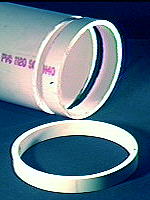
Mount:
6" PVC sch40 pipe (sch80 will have
double the wall thickness). Sawn into a 1" [25 mm] section. File the
pipe section smooth and flat on edges so that it will mate to the lid and
fan.
Drill two holes through the pipe section 180 degrees
apart large enough to pass 6-32 screws. With a 1" [25 mm] section of
pipe, you will need 1.5" [38 mm approx.] screws with nuts and lock washers.
Paint or finish as desired (Ours are flat black to match the
fan).
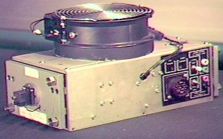
Assembly:
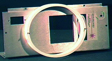
Position mount on lid so
the greatest area of the blades is over the exhaust port of the laser head
as shown in the picture above.
Mark the positions of the screw holes and drill two holes
to match in the laser head cover (remove burrs and rough spots from the
holes).
Once the fan is mounted, make SURE the bolts clear ALL
internal laser parts and DO NOT touch ANY portion of the riser or the
interior of the laser head.. WARNING: Failure to do so WILL destroy your PSU
and your 60X head!!!
Mount fan so air is EXHAUSTED from the riser opening.
(fan airflow indicator pointing away from head - the air blows upwards).
Fan Power
There are 4 wires coming
out the side of the head, usually going to a 4 pin connector. Two of these
carry 110 volts (250 on European 60Xs) and two of the wires are part of the
start interlock circuit.
Connecting the 110 AC wires to the
start Interlock wire will result in fatal damage to the power supply and
head.
The correct procedure is to use a ohm meter to find the
leads. Clip one lead of the ohm meter onto a wire sticking out of the fan
connector, take the other probe and go to the pins of the 22 pin connector
on the side of the head.
If the wire connects to PIN 16 or PIN 20 as indicated by continuity it's 110 AC (or 250 on European 60Xs) power to the fan.
If the wire has continuity to PIN 18 or PIN 21 it's an INTERLOCK WIRE, The laser will not start if the interlock wires are not connected.
Continue testing until
you have identified all four wires as either power or interlock wires.
16 and 20 AC to fan - 18 and 21 Interlock
NOTE: On 60X lasers with interlock switches under the cover, the switch must be depressed (on) for you to get a reading on the meter when testing interlock wires. The thermal switch clamped to the tube must also be in proper working order (normally closed) in order to get a reading.
The factory put a 4 pin connector on the fan for a good reason. By putting a loop of wire on the fan side of the connector to close the interlock circuit, they provided a means for confirming a fan is attached. It would be prudent for the laserist to do so as well, especially if you use a detachable fan. A 60X tube will only survive without damage or change in gas pressure for about about 1 minute when operating at 10 amps without a fan.
WARNING: Incorrect wiring WILL destroy your PSU and your 60X head!!!
Most of the information and ideas in the Hobby Archives have been contributed by hobbyists and experimenters. If you have any comments or ideas to share, please contact us by E-mail.
DISCLAIMER: Some of the information in the Backstage area is provided by the persons or companies named on the relevant page(s). Laser F/X does NOT endorse or recommend any products/services and is NOT responsible for the technical accuracy of the information provided. We provide this information as a service to laserists using the Backstage area.
[ Introduction | Hobby Archives | Hobby FAQ | Laser Construction ]
|
©
1996-2008
Laser
F/X International and LaserFX.com - All rights reserved. |
|