|
Laser
Show Systems - System Design
Compact
Programming System
By L. Michael Roberts
Abstract
The design of a practical, compact 30K laser graphics
programming system based on a modulatable red diode laser and 6800HP
scanners is described. A secondary design criteria was to allow the
use of the programming projector with an external
laser source.
Introduction
For programming laser graphics and animations, it is often
impractical and can be expensive to set-up a whitelight laser. It is
not always necessary to see the images in colours as during digitizing and
programming, the quality of the image, sharp corners, joined lines and the
overall 'look' of the image are more important considerations. The
design objective for this system was to create a programming projector based
on a diode laser, but with sufficient flexibility that it could be used with
other lasers of various types as well.
Design
Constraints
The major constraints in terms of size were; all the
components that had to fit into the case [no outboard electronics], and the
case had to be an 'off the shelf' enclosure to save the expense of having a
custom enclosure manufactured.
The single largest component of the system was the +/- 24 VDC regulated
power supply needed for the scanners. The second largest component was
the scan amps themselves with all other components having much smaller
footprints.
The input connector chosen was an DB25 ILDA standard connector so as to have
maximum compatibility with a variety of graphics and control systems.
|
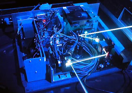
The completed
projector in use with an external whitelight
laser and PCAOM
|
Construction
The enclosure chosen was an 'off the shelf' electronics
cabinet available from a local electronics store. The cabinet was made
of thin formed steel with aluminum front and back panels and measured 16 X
12 X 6 inches [40.5 X 30.5 X 15.5 cm].
The cabinet was not sufficiently rigid to mount optical components in a
stable relationship to one another. A 1/4 inch [.7 cm] baseplate with
the same depth as the enclosure [12" - 30.5 cm] and extending 1.75
inches [4.5 cm] beyond one end of the cabinet was attached to the bottom of
the cabinet. This provided a firm foundation for mounting the power
supply and other components and also provided rigidity for the optics.
In order to provide maximum flexibility and configurability in mounting the
optics, a 'mini' optics plate measuring 10 X 6 inches [25.5 X 15.4 cm] with
holes tapped 1/4-20 on a 1 X 1 inch [2.5 X 2.5 cm] grid was mounted to the
font right quadrant of the projector. This would allow for the
mounting of the diode laser, scanners, steering mirrors and an optional
PCAOM cell if full colour operation with an external laser was desired [the
PCAOM driver would have to be in an outboard enclosure in this
configuration].
The power supply was bolted to the aluminum baseplate through the cabinet at
the far left hand end of the enclosure. In order to save space, a
small PSU board with caps and +5 VDC regulator was mounted inside the 24 VDC
power supply and fed from the positive rail to provide power to the red
diode laser. The scan amps were mounted at the back right hand side of the
cabinet so that the trimmer controls faced outwards and were easily accessible
with the cover off.
The CTI 6800Hp scanners were installed on the standard Cambridge Technology
heatsink. This in turn was mounted on a black anodized L bracket made
of 1/4 inch [.7 cm] aluminum. Heat transfer compound was used at the
junction of the CTI scanner heatsink and the L bracket to insure good
thermal transfer. The L bracket was drilled and tapped with the hole
on the optical axis of the input beam. This allows the entire scanner set on it's
L bracket to be adjusted for vertical image placement. This assembly
was attached with a single screw to another L bracket with slots in the base
designed to pass 1/4-20 screws so that it could be optimally placed and
adjusted into the laser beam.
Components
The photo below shows the completed projector with the
components numbered and the laser path drawn in red for clarity.
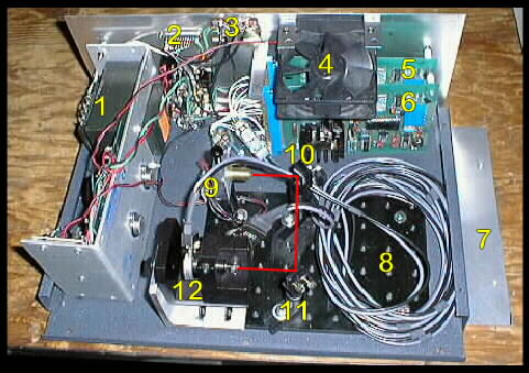
The assembled programming projector shown
with the top cover off.
-
1/ The regulated +/- 24 VDC power supply
for the scanners. At the front left side you can see the top of
the circuit board for the +5 VDC laser power supply.
-
2/ ILDA format DB25 input connector on the
back panel for the scanning signals
-
3/ Input gain control pots to adjust mage
size
-
4/ Cooling fan for the scan amps.
This is a 24VDC fan which was connected to the negative side of the
supply to balance the load as the laser is powered from the positive
side of the supply.
-
5 & 6/ A pair of single channel DLT
9370 scan amplifiers from new Method Lasers. Note that the adjustment
trimmers face outwards for tuning the system.
-
7/ The extension of the baseplate with two
tapped 1/4-20 holes. This is provided so that the projector can be used
with outboard lasers by sending the beam through a hole in the side of
the cabinet.
-
8/ The mini optics plate tapped with 1/4-20
on a 1 X 1" grid for mounting the optical components - there is sufficient
additional space on the right side of the plate for input steering
mirrors and a PCAOM cell if desired.
-
9/ A Spectronika optics post and post
holder mount holding a 30 mW modulatable red laser diode [brass barrel]
from New Method Lasers which is powered from the +5 VDC PSU. The
modulation input is connected via a diode array to the ILDA DB25
connector - the diode array combines all of the 6 colours into one
signal.
-
10 & 11/ A pair of Spectronika OM3/4 optics
mounts with post and post holders. These hold mirrors to steer the
laser beam into the scanners.
-
12/ the CTI 6800Hp scanners mounted on a standard
CTI heatsink and then on an L bracket to allow for vertical adjustment -
the adjustment screw can be seen on the left. That assemble is mounted
on a secondary L bracket with slots for adjustment into the laser beam.
[The large coil of cable to the right is the standard length of cables
as provided by CTI. the author left them intact to avoid cable
capacitance issues.]
Acknowledgments
The author would like to thank Bob Ash of New Method
Lasers
who provided the +/- 24 VDC PSU, modulatable red diode laser and the DLT
scan amps, and also provided technical assistance in tuning the system.
DISCLAIMER:
Some of the information in the Backstage area is provided by the persons or
companies named on the relevant page(s). Laser F/X does NOT endorse or
recommend any products/services and is NOT responsible for the technical
accuracy of the information provided. We provide this information as a
service to laserists using the Backstage area.
[
Introduction - System
Design - Scanning Systems
- Support
Equipment - Laser
Graphics - Show
Production - Pinouts ]
|
