www.LaserFX.com Home Page - CLICK HERE

  Home Page >>> Backstage Area >> Laser Show Systems > Support Equipment

Search LaserFX.com - CLICK HERE Site Map - CLICK HERE
LaserFX.com Home Page
Backstage.LaserFX.com
Laser Safety
Laser Hobbyists
Laser Show Systems

Introduction

System Design

Scanning Systems

Support Equipment

Laser Graphics

Show Production

Pinouts

 
Standards and Practrices
Laser F/X Newsletter
Unclassified Ads
Business Issues
Laser Show Discussions
Archives and Download
Laser Show Resources
Updates Page - CLICK HERE
Member Services - CLICK HERE
LaserFX.com Banner Ads - CLICK HERE
About Laser F/X - CLICK HERE
Contact Us - CLICK HERE


Laser Show Systems - Support Equipment

Spider Box for low power 220 VAC lasers

Abstract

Many smaller air-cooled lasers, and even some lasers up to 5 watts output, need 220-230 VAC for operation but at only 10-15 amps or less. This paper describes a simple "spider box" that can be used to make 220 VAC power from two 110-115 VAC outlets without the use of a heavy step-up transformer.

An example of a spider box

DISCLAIMER: This paper discusses medium and high voltage AC power wiring. The voltages discussed are dangerous and can be lethal - the reader is advised to use caution and standard electrical safety practices when working with AC power. Connection of this device to the AC lines in your area may be subject to approval/certification of the device - check with local authorities before connecting to your power grid.


Introduction

Most lasers that output more than a few milliwatts require 220-230 VAC for operation. In most cases, this means using heavy cables and locating a stove plug or three phase power source for the laser. There are many air-cooled and even a few small water cooled lasers that require fairly low amperages at 220-230 VAC -some less than 15 A for operation.
These can be powered quite simply using a spider box rather then a heavy step-up transformer. A step-up transformer will typically only deliver a little less than half the input amperage [E.G. if a step-up transformer is plugged into a 16 A 115 VAC outlet, it will deliver about 7.5 A at 220-230 VAC]. The spider box overcomes this and allows up to a 15 A laser or laser system to be powered from two U-ground outlets [provided they have 15A or more breakers].
A spider box combines the phases from two 15 A U-ground plugs into 220-230 VAC. Depending on the amperage requirements of your laser, there may be some power left over to run low-load devices such as a projector, controller or laser graphics computer.


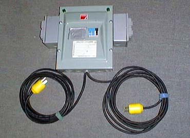
Circuit

The circuit shown below was designed to operate a Spectronika 5 watt CV laser system [which requires about 8 A at 220-230 VAC] as well as providing two 110-115 VAC outlets, one to power the projector and one for the controller and graphics computer. It can be used [with modifications] to power any small laser that draws up to 15 A at 220-230 VAC.

Spider Box schematic diagram

To build the spider box, we used a readily available small 220 V breaker panel capable of holding a maximum of eight single pole breakers. Smaller boxes are available however, this one was an "off the shelf" unit available at Home Depot [and many other hardware/electrical stores]. In the schematic above, the two ground lines are tied together and also attached to the case of the box by means of the grounding strip/terminal. The two neutral lines are also tied together and connected to the neutral terminal strip in the electrical box. The live lines are connected one to each of the live input terminals of the single phase box.
NOTE: The wires in the 14 gauge input cables follow the standard North American colour scheme of green, white and black - the lines are shown as red and black in the schematic for clarity.
A 10 A dual pole breaker was installed in the box and the output side was routed to a 220 V U-ground socket which has two horizontal prongs rather then the vertical prongs typically seen on U-ground sockets. If your laser requires more then 10 A, then a 15A dual pole breaker can be used. A receptacle for this type of plug was mounted into a water resistant, outdoor type, molded plastic receptacle box with spring loaded cover flaps. These are readily available at most electrical and hardware stores and are light weight and durable. A ground connection was made from the U-shaped pin to the grounding strip attached to the interior of the case.
On the opposite side of the breaker box (see photo above) another similar water resistant, outdoor type, molded plastic receptacle box with spring loaded cover flaps was mounted and fitted with two standard U-ground receptacles. Each of these was connected to it's own 5 A breaker to provide protection for the connected equipment. If your laser requires more then 10A of power, these additional receptacles should be eliminated.
NOTE: Some dual 115 VAC receptacle assemblies come with a small metal strip that ties the two neutral and hot lines of the receptacles together. If this is present, it should be removed on the live side so that the outlets function with common ground, common neutral and separate hot lines.
Two 115 VAC neon indicators were mounted to the top of the front of the breaker box and each was wired from one phase to ground (N1 and N2 in the schematic). In the event that the load on the spider box exceeds the capacity of the building socket and a breaker blows, these lights help to determine which of the 115 VAC outlets is at fault so that power can be quickly restored.


Operation

In order for the box to deliver the 220-230 VAC, the two 110-115 VAC U-ground connectors must be plugged into outlets on separate phases, and the building wiring needs to be correct. If the hot and neutral are swapped on one of the wall receptacles, there will be a short. We use a small AC line tester which looks like a large U-ground plug with 3 lights on the back to verify that the building socket is correctly wired before plugging in the box.
By inserting the probes from a multimeter into the 220 VAC socket on the breaker box, we can quickly determine if the outlets are on different phases. When the wall outlets are on the same phase, the voltage reads well below 220. When the wall outlets are on different phases, the meter will read between 208 and 230 VAC depending on the local power supply.
The box has about 3 meters (12 ft) of 14-3 cable for each of the U-ground plugs. In areas well supplied with circuits such as a professional theatre or auditorium, this is often enough to connect to wall receptacles that are on different phases. In some locations, we simply use an additional 10 meter (30 ft) 14-3 U-ground extension cord to extend one of the plugs to a receptacle on another phase that may be at some distance from the spider box. We also carry a couple of 10 Meter (30 ft) 14-3 extension cords with the horizontal prong 220 V plugs and sockets so that we can locate the spider box out of the way at the bottom of the scaffold and run the 220-230 VAC power up to the laser.
NOTE: You should find out what other items are connected to the circuits you intend to use for the spider box so that the total load of your laser system plus other items do not exceed the rated load for the outlets.


Summary

The spider box allows us to power up our 5 watt, air-cooled Copper Vapour laser, the X-Y beam projector, the control console and a graphics computer without the need of a step-up transformer, bulky cables or finding a 220 V connection. It is simple to assemble, weighs less and cost less than a step-up transformer. It can be used to quickly and easily provide 220-230 VAC power for any laser that draws less than 10-15 amps.


DISCLAIMER: Some of the information in the Backstage area is provided by the persons or companies named on the relevant page(s). Laser F/X does NOT endorse or recommend any products/services and is NOT responsible for the technical accuracy of the information provided.  We provide this information as a service to laserists using the Backstage area. 

 [ Introduction - System Design - Scanning Systems - Support Equipment - Laser Graphics - Show Production - Pinouts ]


© 1996-2008 Laser F/X International and LaserFX.com - All rights reserved.
Logos and trademarks are the property of their respective owners - used by permission.