www.LaserFX.com Home Page - CLICK HERE

  Home Page >>> Backstage Area >> Laser Show Systems > Support Equipment

Search LaserFX.com - CLICK HERE Site Map - CLICK HERE
LaserFX.com Home Page
Backstage.LaserFX.com
Laser Safety
Laser Hobbyists
Laser Show Systems

Introduction

System Design

Scanning Systems

Support Equipment

Laser Graphics

Show Production

Pinouts

 
Standards and Practrices
Laser F/X Newsletter
Unclassified Ads
Business Issues
Laser Show Discussions
Archives and Download
Laser Show Resources
Updates Page - CLICK HERE
Member Services - CLICK HERE
LaserFX.com Banner Ads - CLICK HERE
About Laser F/X - CLICK HERE
Contact Us - CLICK HERE


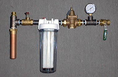
Laser Show Systems - Support Equipment

Basic Water Works

It is desirable to have basic pressure control and filtering of the cooling water fed to laser systems to insure reliable operation.  This article describes a basic water works.

A basic water works for lasers

The photo above shows a basic water works.  At the top left is a garden hose fitting where the water enters the system.  Below that, the long brass object, is a water hammer arrestor.  This is a small chamber fitted with an air bladder that is partially compressed by the water flow and is designed to minimize shocks from uneven water pressure caused by solenoid valves or other spring action valves that 'slam' shut.  Note that the water hammer arrestor must face the input and potential source of shocks to work properly - the output flows at right angles to the arrestor through the T.
The next item is a 3/4 inch ball valve to allow the water to be shut off if the filter should require changing during operation.  This valve should be opened very slowly when the system is first hooked up to allow air to be driven out of the laser system without producing any shocks to the laser cooling jacket.
After the valve, is a filter with disposable cartridge elements which can be replaced when they become clogged.  Use 20 to 50 micron disposable elements.  You can use the regular elements as the more expensive activated charcoal elements are designed to remove odors and tastes, which is not important in this application. Always carry spare filters in your tool kit and change the filter as soon as the colour changes noticeably.
After the water filter, is the adjustable pressure regulator which controls the pressure of the water to the laser.  After the regulator, we have another T fitting with a pressure meter which allows us to observe and adjust the pressure of the water provided to the laser.  The last item is a second 3/4 inch ball valve to control the flow of water to the laser.  This also helps prevent back-flow from the laser in the event that the filter cartridge must be changed during operations.  If your water filter has an air relief valve on the top, you can keep this ball valve valve closed while releasing the water from the filter assembly, and then open it slowly to push the water out of the laser cooling system.

Basic Water Works - Exploded View

The diagram above shows all of the parts required to assemble the basic water works.  Note that all of the threaded joints have at least 2 layers of Teflon tape wrapped over the threads before being screwed together in order to eliminate leaks.  Special care must be taken screwing the metal parts into the water filter assembly as is is made from plastic and the threads can be torn or the housing may be cracked if the pipes are screwed in too far.  When assembling the system, be sure to observe the input and output markings on the filter body so it will function correctly.

1 - Brass garden hose thread to 4/3 IPT thread adapter
2 - 3/4 inch galvanized T fitting
3 - Water Hammer Arrestor - Watts Industries model number SG-075 (or similar)
4 - 3/4 by 2 inch inch galvanized threaded nipple
5 - 3/4 inch bronze ball valve - Watts Industries model number B-6000 3/4 in. (or similar)
6 - 3/4 by 1 inch galvanized threaded nipple
7 - 3/4 inch input and output disposable cartridge filter assembly [available at Home Depot and many other hardware and plumbing supply stores] and 5 or 10 micron filter cartridge.
8 - 3/4 by 1 inch galvanized threaded nipple
9 - Pressure regulator - Watts Industries model number N35BDU (or similar)
10 - 3/4 by 1 inch galvanized threaded nipple
11 - 3/4 inch galvanized T fitting
12 - 3/4 inch to 1/2 inch galvanized adapter bushing
13 - Water pressure meter measures in the 0 to 60 PSI range
14 - 3/4 by 2 inch inch galvanized threaded nipple
15 - 3/4 inch bronze ball valve - Watts Industries model number B-6000 3/4 in. (or similar)
16 - Brass 4/3 IPT thread to garden hose thread adapter


DISCLAIMER: Some of the information in the Backstage area is provided by the persons or companies named on the relevant page(s). Laser F/X does NOT endorse or recommend any products/services and is NOT responsible for the technical accuracy of the information provided.  We provide this information as a service to laserists using the Backstage area. 

 [ Introduction - System Design - Scanning Systems - Support Equipment - Laser Graphics - Show Production - Pinouts ]


© 1996-2008 Laser F/X International and LaserFX.com - All rights reserved.
Logos and trademarks are the property of their respective owners - used by permission.